Sunday, June 30, 2013

Animate3 - the commands (part 2)

This posting continues the explanation of Animate3 commands. See here for the first part of the Animate3 description, and here for the introductory text with a simple animation.

Here is an overview over this posting's contents:


< ... reading a parts file


Syntax:

< filename

Explanation


< is a non-blocking command. This command reads in a parts file. I have explained its syntax and semantics already in the first posting about Animate3.


~ ... controlling system effects (script output)


Syntax:

~ filename
or
~ +
or
~ –

Explanation


~ is a non-blocking command.
  • ~ + means that effects in the operating system take place.
For the current implementation, this means that corresponding commands are written into the output batch file. Other implementations might directly invoke the effects.
  • ~ – means that effects in the operating system are suppressed. However, all other computations (running actions, initializing and incrementing value generators) are done. This command is useful if one wants to debug a later part of an animation, as the previous, time-consuming ImageMagick calls are skipped.
  • ~ filename sets the name of the output batch file. Moreover, it also has the effect of ~ +.
By default, system effects are enabled (i.e., the batch script is written). The default output file in the current implementation is the standard output (/dev/stdout in AWK terminology).


| ... Executing parallel subactions


Syntax:


| [ . | framelimit ] [ action ]*
where action is
actionscriptfile [ repetitions | . ]
or
|


Valid parameters:


  • framelimit and repetitions are integral numbers or expressions—see this explanation of expressions for the latter.
  • actionscriptfile is the name of a script file.
The actions in the | command are called "actions mentioned by the | command."

Explanation


| is a blocking command.

Before the command is executed, all expressions are evaluated and interpolated into the command.

The first form of the command then continues with all the mentioned actions in the following manner:
  • If no action is mentioned (i.e., the command consists only of a bar and a dot or a number), the previous | command is re-executed, but with the given framelimit (be it . or a number), according to the following rules.
  • If a mentioned action is currently active with some blocking current command, it continues to execute with this command.
  • If a mentioned action is currently active, but is not at a blocking command, it must be at its end (otherwise, this action here could not be executing this | command). In this case, if the action has been executed fewer than repetition times since this | command had been started, or if a dot is given as repetitions, the action remains active, but its current command is reset to its first command.
  • If a mentioned action is currently not active, it is started: Its lines are read in from the given file, it becomes active, and its current command is set to its first command. By convention, the name of the file is also the name of the action.
  • If there was a previous | command in the same script where this | command is located, and there are still active actions from that previous | command that are not mentioned in this | command, those actions are made stopped: They are made inactive so that their state is forgotten.
The command finishes (i.e., allows the script to execute its next command) when one of the following happens:
  • Either all actions where an explicit repetition number is given (these are called "controlling actions" of this command) are no longer active.
  • Or a framelimit is present, and the actions mentioned in this | command have created or contributed to more than framelimit frames since the | command became the current command.
It is in error to put an action into a | command if the same action is currently active in another | command (of a concurrently executing action).

A | command is said to surround another command if that other command is in one of the scripts mentioned in the | command; or if a  | command in one of the mentioned scripts surrounds that other command.

The second form of the command deactivates all currently active actions and then stops the frame-generating loop. This is probably never used in normal script (except maybe for debugging), but it is necessary for finishing the outermost script that is created from the command line parameters: A call to the Animate3 compiler with script parameters script1.an3 ... scriptN.an3 is transformed into the following script (with internal name .):
| . script1.an3 1
...
| . scriptN.an3 1
|
This script is then made active, and finally, the frame-generating loop is started. When the script reaches the final | command, it will terminate that loop.


= ... defining the view of a scene


Syntax:


= [ . | framecount ] sceneX sceneY sceneW sceneH scenefile scenepixelW [ scenepixelH | . ]

Valid parameters:


  • scenefile is an arbitrary string (without white space) which can include value expressions.
  • All other parameters must be real numbers or value expressions—see this explanation of expressions for the latter.

Explanation:


= is a blocking command.

This command is a sort of "back end" for the & command: For a certain number of frames, it provides parameters for frame creation. The command remains active
  • indefinitely (but it can be deactivated by surrounding | commands—see| command) if no framecount is given.
  • for framecount loops of the frame-generating loop after is has become the current command of its script.
I have explained the semantics of this command already in the first Animate3 posting (more or less).


& ... creating frames from parts


Syntax:


& [ framecount | . ] [ piece with transformations ]*
where piece with transformations is
partname [ transformation ]*
where transformation is one of the following:
  • @ . . Angle
  • @ X Y Angle
  • > dX dY
  • ^ . . sX dX sY dY
  • ^ X Y sX dX sY dY
There is also an abbreviated form:
& framecount

Valid parameters:


  • partname must be the name of a part that is present in one of the parts files that have been read on before this command is encountered.
  • All other parameters must be real numbers or value expressions—see this explanation of expressions for the latter.

Explanation:


& is a blocking command.

The & command contributes to framecount frames by placing the mentioned parts with their transformations. The number of frames where the command actually contributes might be less than framecount if a surrounding | command is stopped short—see| command. If . is given instead of a numeric framecount, the command contributes to indefinitely many frames, until it is stopped short by a surrounding | command.

The abbreviated form repeats the command from the preceding & command. This is sometimes useful concept: One can set up a "model" in a large & command with framecount zero, using various variables. Then, using an interleaved sequence of variable commands and abbreviated &s, the model becomes animated. However, with the introduction of | commands, this is no longer that helpful.

A part can be used more than once in an & command. Each usage counts as a separate "piece" that is transformed independently of the other pieces, even those stemming from the same part. Each piece starts at the same position as it has in its layer file. If there are transformations given for a piece, they modify it in the given order as follows:
  • @ . . Angle rotates the piece around the part's pivot point by Angle degrees. A positive angle corresponds to a clockwise movement (in contrast to the mathematical convention, where positive angles are directed counterclockwise).
  • @ X Y Angle rotates the piece around the point (X,Y) by Angle degrees. Again, a positive angle corresponds to a clockwise movement.
  • > dX dY shifts the piece by (dX,dY).
  • ^ . . sX dX sY dY stretches the piece from its pivot point by factors 1 + dX/sX in x direction and 1 + dY/sY in y direction.
  • ^ X Y sX dX sY dY stretches the piece from center (X,Y) by factors 1 + dX/sX in x direction and 1 + dY/sY in y direction.


$ ... creating frames with shell commands


Syntax:


$ [ framecount | . ] any text to end of line

Valid parameters:


Explanation:


$ is a blocking command.

Besides the more advanced & command, there is still the old $ command from the first animation language. Of course, because of the & command, its usage has been greatly diminished. However, it is e.g. useful to add the final ffmpeg calls to the created scripts, or maybe add some file handling in between. And, of course, one can write exploratory tests with it that show only the working of the scheduler, i.e., the machinery interpreting the | commands, by simply replacing & with $.

The & command executes for framecount iterations of frame-generating loops. The number of iterations might be less than framecount if a surrounding | command is stopped short—see| command. If . is given instead of a numeric framecount, the command does not end by itself, but executes for indefinitely many iterations of the frame-generation loop until it is stopped short by a surrounding | command.


What is not in Animate3


At least the following concepts that appear valuable are missing from Animate3. Some of them I considered in the first draft, but then I opted for a smaller language, at least for the moment:
  • compound parts
  • local variables
  • cranks with sliders
  • non-affine transformations
  • fluids
  • color changes
  • 3D
Compound parts would allow something like "rotate part1, overlay it with part2, and then shift (or rotate, or stretch) these two together". ImageMagick can do this, either by using a stack or by using parentheses. However, I think that another abstraction concept is right now not the way to go—it might be a future feature.

The value generators (or "variables," if you like) in Animate3 are global objects. There is no "action scope" or the like associated with them: Any action can use any generator, and any action can redefine any value generator. This sounds bad. Still, it is useful to pass value generators around. If local variables were introduced, I would probably also have to introduce some concept of parameter passing between actions, and this is much work. Rather, I suggest (and try) to name variables according to the part and/or action where they are defined and used.
Maybe one clarification is needed here: In contrast to programming languages and maybe other, larger animation systems, Animate3 is not intended for building some sort of reusable action libraries or the like. The idea is to always start with a new CAD drawing (or set of drawings) which has all the parts at about the right places, and then get these parts moving around. Therefore, that much abstraction is not needed (and I doubt that the | operator will be used with more than a nesting depth of one or maybe two).
Slider-cranks-mechanisms are important elements in many mechanical devices. However, the motion of such a mechanism cannot be easily described with trigonometric formulas (the emphasis is on easily). It will probably soon be necessary to introduce some basic expressions in Animate3 that can compute a slider's displacement from the corresponding crank's angle and vice versa.

Some machine elements cannot be described by affine transformations. One example is a bending spring (such springs were often used in the striking mechanisms of old watch movements), but also diaphragms in pneumatic or hydraulic devices are of this sort. Such deformations can be described with higher-order tensors, and ImageMagick supports quite a few such transformations out of the box. However, these transformations do not interact well with keeping the origin of an image, which is needed for putting the deformed element back into the whole frame. At least, it should possible to pre-compute the deformed forms into files that can then be included in frames—this sounds like a feature with high priority.

When one starts to animate pneumatic or hydraulic devices, it is necessary to show the flow of some volume of gas or fluid through various pipes and holes and crevices. There is no support for this right now in Animate3 (and I do not yet know how such a flow can be described and then transformed into a sequence of image parts).

In the same vein, it should be possible to change the color of an element based on some value generators' values. At least fluids and gases should sometimes be shown in blue or red (for cold and hot; or low or high pressure).

Last (and least, I'd say), one could think about animations in 3D. However, our computer screens will, for a long time, remain 2D, and therefore an animation designer has to think about the 2D layout anyway: A technically perfect 3D animation where some pieces are hidden behind others will have a much lower explanation value than a well laid out 2D animation! Therefore, 3D is not really an important feature for the sort of tool that Animate3 wants to be.


This concludes my description of the Animate3 language. If someone is interested in the code of the compiler, maybe this diagram of its internal data structures is of some help. More explanations and comments must wait, because I will now concentrate on creating that "5007" animation with Animate3!

Animate3 - the commands (part 1)

In the previous posting, I presented a system for creating two-dimensional technical animations.

The major description for such an animation is written in a small language called Animate3, whose elements I will start to explain in this posting.

The language has only nine different commands that are used to create a batch file (or shell script) that creates the actual animation.

Here is an overview of the contents of this posting:


The execution model


The semantics of the language can—as for any language—only be explained by referring to an "execution model," i.e., some interpreter that reacts to the given commands. The previous posting already contained a brief description of this execution model, but I will repeat it here for convenience and extend it with a few details.

An Animate3 script is executed in the following context:
  • There is a file system where files can be read and written.
  • There is an operating system that has at least the following commands: (a) A no-op (comment) command; (b) a check for file and directory existence; (c) creation of directories.
  • ImageMagick is installed in version 6.8.1 or higher.
In addition, each execution knows how to produce five "effects" in the operating system:
  • (A) Execute the no-op (comment) command with some additional information.
  • (B) Call some command if a file is missing.
  • (C) Call ImageMagick's convert command.
  • (D) Create a directory if it is missing.
  • (E) Create a file path from a directory name and a file name.
The semantics of the language is described in the following model: At every time, the state of the execution consists of
  • a set of scalar value generators, where each (a) is either initialized or uninitialized; and has (b) a current real-number value; (c) a generating command; and (d) an output format for its value;
  • a set of vector value generators, where each (a) is either initialized or uninitialized; and has (b) a pair of real numbers, called X and Y, as its value; and (c) a generating command;
  • a set of active actions, where each has (a) a list of commands; (b) a current command; (d) a number of "open frames;" (e) a number of "open repetitions;" and (f) possibly (and usually) a parent action;
  • possibly a selected "scene action," which defines the size of the scene's view port and, additionally, the name of a frame file;
  • a flag "frame generation is on/off."
The interpretation of each command in each active action happens in an endless frame-generation loop whose body consists of three steps:
  • (STEP EXECUTE) First, each active action executes all its commands up to the first "blocking command." This can either be a frame-emitting command, or it is the final command of the action when the number of open repetitions of the action has been exhausted.
  • (STEP DRAW) Some frame-emitting commands (specifically, & commands) may have created "pieces," i.e., parts from the input graphics files in some position or other transformation. In the second step of the frame generation cycle, these pieces are assembled into the frame file.
  • (STEP INCREMENT) Finally, in the third step, all value generators (scalar and vector) are "incremented," i.e., their current values are updated by the respective generating command.
Of course, there is one command that stops this "endless" loop so that frame generation comes to an end.

The following description of all Animate3 commands will explain, for each command, which part of the state of execution is changed in what way during which of three steps of the frame-generation loop.

Some remarks about the current implementation


The current implementation of the Animate3 system consists of a "compiler" that reads one or more Animate3 scripts and emits a batch file or shell script. By default, this emitted file is a Windows .bat file; however, it is easy to pass a few parameters to the compiler to emit other sorts of command scripts.
Because of the intermediate batch file, the state described above has an additional component, namely the current name of the batch file written. A different implementation of Animate3 might not need this.
The resulting batch file is then executed on the operating system, which creates the frames of the animation. These frames can be assembled into some animation file by a call e.g. to FFmpeg.

The current Animate3 compiler is written as a Gnu-AWK-3.1.6 script of exactly 1000 lines of code. Of course, it would be possible to implement it in any other programming language—and I even think that this would be a nice exercise: On the one hand, Animate3 is quite small. On the other hand, Animate3 contains interesting and important basic concepts from at least three areas of computer science, namely (a) computer graphics, (b) task scheduling and (c) language parsing. Therefore, any new implementation should be interesting to write. Also, it should be possible to tackle the small language with formal methods—formal semantics, formal correctness and termination proofs of an implementation, development of covering test cases etc. But I digress—let me return to the language proper.

The Animate3 compiler is called using the Gnu-AWK executable as follows:
gawk -f animate3.awk optional_variable_assignments script_file ...
Five variables control the output of the Animate3 compiler.
  • REM is a prefix for emitted lines that are comments—used for effect (A) (see above). Its default value is @REM.
  • CREATE is a C-style format that is used to call a command if a file is not existing, i.e., for effect (B). It must contain %s exactly twice. The first %s is replaced with the name of the file to be created, the second %s is replaced with a command that (usually) creates that tile. CREATE's default value is if not exist %s %s\n.
  • CONVERT is a string that calls ImageMagick's convert command—effect (C). Its default value is convert.
  • MKDIR is a C-style format that is used to create a non-existing directory, i.e., for effect (D). It must contain %s exactly once or twice. Each %s is replaced with the name of the directory to be created. MKDIR's default value is if not exist %s mkdir %s\n.
  • PATHSEP is a string that separates a directory name from a file name—used for effect (E). Its default value is \.
Here is an example call that replaces some of these values:
gawk -f animate3.awk -v REM="#" -v CREATE="if [ -f %s ] then %s fi" -v MKDIR="if [ -d %s ] then md %s fi" -v PATHSEP=/ script.an3
Moreover, there are two variables that control debugging output:
  • DEBUGOUT is a file where quite a lot of debugging output is written. Its default value is the empty string.
  • DEBUGDETAIL is a regular expression that can be used to filter debugging output. Its default value is also the empty string. Useful values might be function names or generator names—but I never used it myself; instead, I worked with the complete debugging output.

All the Animate3 commands


Animate3 has nine different commands:
  • # ... a comment line that is copied to the result script.
  • ! ... definition of a scalar value generator
  • % ... definition of a vector value generator
  • <... reading a parts file
  • ~ ... controlling output
  • | ... starting parallel subactions; and stopping the frame-generation loop
  • = ... defining the view of a scene
  • & ... creating frames from parts
  • $ ... creating frames with shell commands (useful to execute arbitrary code)
Lines that start with one of these nine characters are interpreted. All other lines in a script are ignored.

A command can be broken over more lines by appending a \ (backslash) to each line that is continued in the next line. This is especially useful for the | and & commands.

Here follows a description of all nine commands, including some simple example usages. For each command, the following is provided:
  • The syntax explains what valid commands look like. Italic parts indicate variable parts; the allowed values are explained later. | is used to denote alternatives, * for repetitions (including zero occurrences), and brackets [ and ] define the scope of | and *.
  • The legitimate values for the variable parts are explained next.
  • The subsequent explanation explains what the command does in the three phases of the frame-generating loop.


# ... a comment that is copied to the result script.


Syntax:

# arbitrary text to end of line


Explanation:


# is a non-blocking command.

The text is copied into the resulting batch script via effect (A) above. This is helpful for script debugging, as one can line up the input script with the generated batch commands.


! ... definition of a scalar value generator


Syntax:

!name [ init | . ] step [ modulus | . ]
or
!name init


Valid parameters:

  • name must be a non-empty sequence containing only the letters A...Z and a...z, digits 0...9, and underscores.
  • init, step, and modulus must be real numbers or value expressions—see here for the latter.


Explanation:


! is a non-blocking command.

After a definition—also a re-definition—, a value generator is in the uninitialized state, with one exception: When a dot is given as the first parameter, and additionally the generator was already initialized, it remains in the initialized state.

In STEP EXECUTE, the definition will only have the effect that the definition is remembered.

In STEP INCREMENT, the generator will be initialized (see below) if it is not yet initialized. Then, the definition will have the following effect:
  • If it is the first form, the generator's value will be replaced with ((value + step) modulo modulus), if modulus is given; or (value + step) if there is a dot at the last position.
  • If it is of the second form, the generator's value will be replaced with the value of init.
The second form is of course not useful when init is a fixed number. However, it is very useful if init is an expression that uses other values that are modified in STEP INCREMENT. The access definition below guarantees that a value generator is incremented before it is accessed during STEP INCREMENT.
The value of a scalar value generator can be accessed in other commands using the syntax !name.
Also, the change to the value in the last STEP INCREMENT can be accessed in other commands using the syntax !name' (with a trailing single quote).

Such an access can happen either in STEP EXECUTE (in =, $, and & commands) or in STEP INCREMENT because of its usage in the command of a scalar or vector generator. Each such access has two consequences:

 a. First, if the value generator is uninitialized, the value will be set to the value of the expression passed as init (for expressions, see later). When this expression in turn contains accesses to other value generators (scalar or vector), this will recursively have the same effects on the accessed generators before the current access. If there is a cycle in this dependency graph, the effect is undefined.
The actual implementation will initialize some arbitrary generator to zero and continue from there.
If instead of init a dot is present, the value will remain as it was before (also an "uninitialized" generator can have a value!). If it had no value up to now, the value is set to zero.
Moreover, if a modulus is provided, the format of the generator is set to "integer output with the number of digits of the modulus's integral part, using leading zeros."
For example, a modulus of 137 will create a format "integer output with three digits and leading zeros." A value of 27 will then be output as 027.
If no modulus is given, the format of the generator is "real number output with as few digits as possible".
The actual implementation uses C-style formats %0md for the first case, where m is the number of digits of the modulus' integral part; and .6g for the second case.
 b. Then, the value is "interpolated" (inserted) in the accessing command using the format.


% ... definition of a vector value generator


Syntax:

%Name [ initX | . ] [ initY | . ] stepX stepY
or
%Name [ initX | . ] [ initY | . ] %vectorpivot angleStep
or
%Name [ initX | . ] [ initY | . ] partpivot angleStep
or
%Name initX initY


Valid parameters:

  • name must be a non-empty sequence containing only the letters A...Z and a...z, digits 0...9, and underscores.
  • %vectorpivot must be a defined vector value generator.
  • partpivot must be the name of a part that has a pivot point (see < command for reading a parts file).
  • All other parameters must be real numbers or value expressions—see here for the latter.


Explanation:


% is a non-blocking command.

After a definition—also a re-definition—, a value generator is in the uninitialized state, with one exception: When dots are given as the first two parameters, and additionally the generator was already initialized, it remains in the initialized state.

In STEP EXECUTE, the definition will only have the effect that the definition is remembered.

In STEP INCREMENT, the generator will be initialized (see below) if it is not yet initialized. Then, the definition will have the following effect:
  • If it is the first form, the generator's X value will be replaced with the value of (X + stepX); and its Y value will be replaced with the value of (Y + stepY).
  • If it is of the second form, the generator's (X,Y) pair will be replaced with the pair arrived when rotating (X,Y) by angleStep degrees around the current (X,Y) pair of the %vectorpivot vector value generator. A positive angleStep will rotate (X,Y) clockwise.
  • If it is of the third form, the generator's (X,Y) pair will be replaced with the pair arrived when rotating (X,Y) by angleStep degrees around the pivot point of part partpivot according to a previously read partsfile (see command <). Also here, a positive angleStep will rotate (X,Y) clockwise.
  • If it is of the fourth form, the generator's (X,Y) pair will be replaced with the values of the pair (initX, initY).
The fourth form is not useful when initX and initY are fixed numbers. However, it is very useful if initX or initY are expressions that use other values that are modified in STEP INCREMENT. The access definition below guarantees that a value generator is incremented before it is accessed during STEP INCREMENT.
The values of a vector value generator can be accessed in other commands using the syntax %name:x (for the X value) and %name:y (for the Y value).
Also, the changes to these values in the last STEP INCREMENT can be accessed in other commands using the syntax %name:x' or %name:y' (with added single quotes).

Such an access can happen either in STEP EXECUTE (in =, $, and & commands) or in STEP INCREMENT because of its usage in the command of a scalar or vector generator. Each such access has two consequences:

a. First, if the value generator is uninitialized, the value pair will be set to the pair of values of the expressions passed as initX and initY (for expressions, see later). When one of these expression in turn contains accesses to other value generators (scalar or vector), this will recursively have the same effects on the accessed generators before the current access. If there is a cycle in this dependency graph, the effect is undefined.
The actual implementation will initialize some arbitrary generator to zero and continue from there.
If instead of initX a dot is present, the X value will remain as it was before (also an "uninitialized" generator can have a value!). If it had no value up to now, X is set to zero. The same holds for the Y value.

b. Then, the value is "interpolated" (inserted) in the accessing command as a real number.


Expressions


Commands can contain expressions that compute values from other values. The value of such an expression is always a single real-valued number.

Simple expressions are direct references to values in value generators or to coordinates of parts. They can be used directly in commands:
  • !name for the value of scalar generator !name
  • !name' for the last value change of scalar generator !name
  • %name:x for the X value of vector generator %name
  • %name:y for the Y value of vector generator %name
  • %name:x' for the last change of the X value of vector generator %name
  • %name:y' for the last change of the Y value of vector generator %name
  • name:x for the x coordinate of the left upper anchor point of part name
  • name:y for the y coordinate of the left upper anchor point of part name
  • name:w for the width of the bounding box of part name
  • name:h for the height of the bounding box of part name
  • name~x for the x coordinate of the pivot point of part name
  • name~y for the y coordinate of the pivot point of part name
  • name~w for the horizontal offset of the pivot point from the left upper anchor point of part name
  • name~h for the vertical offset of the pivot point from the left upper anchor point of part name
However, it is also possible to write more complex expressions. Such a complex expression must be enclosed in curly braces { and }. Because no part of the expression language itself contains braces, an expression always extends from a { to a }. Here is the syntax and semantics of the expression language:

Expression


An expression can consist of the following symbols:
  • simple numbers, consisting of digits (0...9) and at most one decimal point;
  • one of the six possible simple expressions from a value generator;
  • one of the eight possible simple expressions from a part's coordinates;
  • operators +, –, *, /, \, and the combined operator ?: with range symbol ..;
  • parentheses ( and );
  • the symbols sin, cos, tan, asin, acos and atan2.
In an expression, there can be whitespace between symbols, but it is ok if there is no whitespace at all between two symbols. Thus, the following are valid (and equivalent) expressions:
{90*sin!lever_A}
{ 90 * sin   !lever_A }
The syntax of an expression is as follows:
expression ::=
    sum |
    sum ? range : sum [ ? range : sum ]* : sum
where range is defined as follows:
range ::= [ sum ] .. [ sum ]
An expression is
  • either a simple sum; in this case the value of the expression is the value of the sum;
  • or a sum with following range-sum pairs. In this case, the sum is checked against all ranges in order. If it is in a range, the sum after the corresponding colon is the value of the expression. If it does not fall into any range, the expression's value is the value of the last sum.
For ranges, the semantics is as follows:
  • If the first sum is missing, its value is assumed to be –1 ⋅ 1099.
  • If the second sum is missing, its value is assumed to be +1 ⋅ 1099.
  • A sum is "in" the range if its value is at least as large as the first sum; and at most as large as the second sum. However, if the second sum is smaller than the first, both are reversed before the check is made.

Sum


The syntax of a sum is as follows:
sum ::= term [ [ + | – ] term ]*
A sum is a sequence of terms, connected with + and –. The value of the sum is the usual arithmetic value of this sequence, i.e., the terms are evaluated and summed or subtracted from left to right.

Term


The syntax of a term is (here, the first asterisk is meant to be the character *, whereas the second one is the meta symbol for repetition, as in other syntax rules in this posting):
term ::= factor [ [ * | / | \ ] factor ]*
A term is a sequence of factors, connected with *, /, and \ (modulus). The value of the term is the usual arithmetic value of this sequence, i.e., the factors are evaluated and multiplied, divided, or "remaindered" into the first factor.

Factor


The syntax of a factor is:
factor ::=
    number |
    value_generator_value |
    part_value |
    ( expression ) |
    – factor |
    sin factor |
    cos factor |
    tan factor |
    atan2 factor factor |
    asin factor |
    acos factor
A factor's value is determined as follows:
  • simple number: The value of the factor is the decimal value of the number;
  • one of the six simple expressions from a value generator: The value of the factor is as defined above.
  • one of the eight simple expressions from part's coordinates: The value of the factor is as defined above.
  • parenthesized expression: The value of the factor is the value of the expression.
  • factor with a preceding minus: The value of the whole factor is the negative value of the inner factor.
  • sine expression: The value of the factor is the sine of the value of the inner factor, interpreted as a degree value. Thus, sin 90 is the value 1 (one).
  • cosine expression: The value of the factor is the cosine of the value of the inner factor, interpreted as a degree value. Thus, cos 180 is the value  –1 (minus one).
  • tangent expression: The value of the factor is the tangent of the value of the inner factor, interpreted as a degree value. Thus, tan 45 is the value  1 (one).
  • arc tangent expression: The value of the factor is the arc tangent of the first factor divided by the second as an angle in degrees. Thus, atan2 3 3 is 45.
  • arc sine expression: The value of the factor is the arc sine of the inner factor. Thus, asin 1 is 90.
  • arc cosine expression: The value of the factor is the arc cosine of the inner factor. Thus, acos 1 is 0.
That is all that can be said about expressions.

The description of Animate3 is continued in this posting.

Saturday, June 29, 2013

Animate3 - a new small animation language

Half a year ago, I designed a small language that helped me create a few animations of mechanical machinery. For some time now, I have planned to create an animation of a larger apparatus, namely the standard Austrian mechanical railway interlocking type "5007".

However, it became clear very quickly that I needed much more support for this new animation. After all, my very much simplified drawing of this device contains around 80 movable parts, and I am not inclined to draw each one separately and then write computations to move them to the required coordinates! Rather, I wanted a more streamlined process:
  • I would draw the whole apparatus in a single "big diagram".
  • Then, I would assign a layer to each part (the "Z order").
  • Exporting each layer as PNG file, it would now be possible to extract each part from that file if its coordinates were known—which I would indicate by simple diagonal lines that would end up in a "parts description file".
  • For assembling movements from these parts, I wanted an extended small language that could do about the following:
    • Generate scalar and vector values (like the old animation language).
    • Instead of directly calling ImageMagick's convert, simple shortcuts should define the parts' movements. For example, "@ 30" means "rotate by 30 degrees".
    • A frame sequence shold be built by assembling separately defined actions than can even run in parallel. For example, one "action" could be the rotation of an electric generator, whereas in another action an electro-magnet would attract its anchor. Defining the actions separately and then running them in parallel allows me to reuse the actions in other scenarios, e.g. when the line from the generator to the magnet is interrupted: Then only the generator would turn, but the anchor would remain stationary.
    • ImageMagick's convert is not very fast, especially if large pixel images are involved. Because I want to zoom in to parts in some scenes, my raw CAD diagrams usually have 8410x5194 pixels. However, this means that scenes encompassing many parts are much too fine-grained, and hence the parts computations may take long. Therefore, it is necessary to compute a part at a certain position only once, i.e., the result should be cached somewhere.
    • Last but not least, the implementation of the supporting software should be as small as possible.
Just to be clear, this is still an animation engine (and a very small one), not a physics engine. It is still my problem to assign correct coordinates to each part. And it is a purely two-dimensional animation engine.

In the following, I will describe the new animation process, at least as a reference for me, but maybe someone else is also interested in this "small language adventure." As a running example, I'll use a simple latching mechanism: A lever can push a rod with a cut. When the lever is pushed far enough, a weight will drop into the cut and lock the rod in position, while the lever is pushed back by a spring.

Here is an overview over what will be explained in this posting:

Drawing it


Here is the initial diagram I drew:


Creating the Layer PNGs


In a next step, the elements of the diagram are put into layers. The pink weight will of course be in its own lower layer. But moreover, I also put pieces that touch each other into separate layer files because I can then more easily "cut them out"—I'll show this in a minute. For this contraption, two layers L1 and L2 are sufficient:
  • L2 is the lower layer—the pink block must be in it to be behind the green rod.

  • L1 is the upper layer—the green rod is in it. All the other parts are put in the layers so that no two adjacent parts are in the same layer:


From this CAD drawing, I now create a PNG for each layer. For this, I use PDFCreator with a special profile that prints 254 dots per inch. By this, one dot in the PNG corresponds to exactly 0.1mm in the CAD drawing (as 1" equals 25.4mm) so that I can line up coordinates in the PNG and in my CAD drawing more or less easily (the "more or less" comes from the fact that my CAD diagrams have their origin at the lower left corner, whereas the PNGs created by PDFCreator have their origin at the upper left corner).


Unfortunately, the PNGs coming out of PDFCreator are vertically oriented even if printed in landscape mode—I do not know why, but rotating then by 90° them with Windows Image Viewer is easy enough:


By convention, the names of the layer PNG files also define the Z order when sorted alphabetically. Therefore, parts in layer file L1.png will be drawn above parts from layer file L2.png.


Creating the parts list


Besides the layer PNGs, the Animate3 compiler needs as its input a parts list (or a few of them). The information collected in this list is, for each part:
  • A name for the part
  • From which layer file it is to be extracted
  • Its coordinates in the layer file.
Actually, the syntax of the file is a little more complicated:
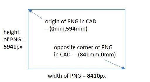
  • A first line indicates width and height of the layer PNG files (all must have the same size); and then the coordinates of the PNG files' origin and opposite corner in CAD coordinates. Here is a typical first line:
    8410 5941 0 594 841 0 
    This corresponds to the following coordinates:
    Then, there are the parts lines:
    • Lines starting with # and empty lines are ignored.
    • A simple part line looks like this:
    • Groupname partname layerfile x1 y1 x2 y2 
      The actual part name is the groupname plus the partname, separated by an underscore. If a single dot is given as the groupname, the previous groupname is used. If a single dot is given as partname, it is omitted in the actual part name. This creates somewhat nicer part lists, IMHO.
      The layerfile information can be also be replaced with a single dot. In that case, the part is not cut out form a file, does not have a layer and can therefore never be used in a frame. However, this feature is useful to define e.g. scene windows ("viewports") in the CAD drawing whose coordinates can then be used directly in the script—see examples below.
      Finally, the two pairs of x and y coordinates define a rectangle which is used cut the part from the layer file. The coordinates given are CAD coordinates which are translated to pixel coordinates using the six values given in the first line of the parts file. I'll show in a moment how I get these CAD coordinates somewhat efficiently.
    • Besides using a simple part line, it is alternatively also possible to define a part with a pivoted part line. It has four more coordinates x3, y3, x4, and y4, which define a pivot point in a somewhat intricate way: Two of the first four coordinates must be equal to two of the last four coordinates—and exactly that equal pair of coordinates defines the pivot point. The remaining four coordinates define the surrounding rectangle. The reason for this strange definition will become clear in the example.
Now, let us create the parts file for the demo machine. First, we write a simple text file that contains the header line and then parts' names and the layers:
8410 5941 0  594  841  0

rod .           L1.png
.   spring      L2.png
.   springblock L1.png
lever .         L2.png
.   washer      L1.png
.   spring      L2.png
.   springblock L1.png
.   stop        L1.png
weight .        L2.png
view   .        .
The first three parts will be called "rod", "rod_spring" and "rod_springblock" when we use them in an animation.

Now, we have to add the coordinates defining the parts. For this, I add a new layer to my CAD drawing and draw diagonal anchor lines "covering" each part, using the CAD program's crosshair. The following screenshot shows three such anchor lines in light green, and you can see that I drew them quite roughly—from somewhere "left above" the part to somewhere "below right." As long as no other part is also in the rectangle thus defined, this identifies each part uniquely:


At least for our lever, we need a definition of the pivot. For this, we draw two anchor lines that meet at the pivot. As explained above, their common point will define the lever's pivot:


Here is a complete coverage of all parts with green anchor lines. Both springs have also gotten pivot points (at their stationary end), and I have added a long line traversing all parts which can be used to define the view (we'll see later how):


How do we get the lines' coordinates into the parts file? This depends on the CAD tool—for example, it might have an export function that can be used on the parts lines' layer. My CAD program doesn't, so I had to extract this information with a Windows script. I use AutoHotkey with a simple script which I use as follows:
  • I open the parts file with Notepad.
  • One after the other (in the order in the parts file), I select the lines in the CAD drawing while having open an "object information" dialog. Hitting "windows space" starts an AutoHotkey script that selects and copies each coordinate, activates the notepad window and pastes the copied coordinate into it. For objects with pivots, I use a "go back to previous line" autohotkey script between copying the data of the two adjacent lines. After some practicing, one gets quite fast with copying over the lines' coordinates into the parts file.
Here is the resulting completed parts file, which we save in AnimateDemoParts.txt. It is untypical that all the coordinates are integral numbers—the reason here is that the model is so simple that I only put the parts at grid points in the CAD drawing:
8410 5941 0  594  841  0

rod .           L1.png  70   480  330  420
.   spring      L2.png  420  440  310  480  430  420  420  440
.   springblock L1.png  410  480  450  420
lever .         L2.png  50   550  90   270  90   270  110  240
.   washer      L1.png  110  390  130  320
.   spring      L2.png  220  350  110  390  230  330  220  350
.   springblock L1.png  210  390  250  330
.   stop        L1.png  40   390  70  330
weight .        L2.png  310  510  240  390
view   .        .       20  560 460  230


Writing an animation


The major feature of the new animation process is a new language whose features I have outlined above. For obscure reasons, I call it "Animate3". The following sections explains this small language with some examples. Later, I might write a "reference manual" for this small language.

An Animate3 script is compiled to a batch script (Windows .bat file or something similar) that can then be run to create the actual frames of the animation.


A short overview


The most important commands in a script emit one or more frames. A simple command might look like this:
& 50 lever @ . . !lever_A
This is read as follows:
Create (&) 50 frames by rotating (@) part lever around its pivot point (. .) by !lever_A degrees  at its original position in the CAD drawing.
So that the lever actually rotates, the value !lever_A must be defined so that it is incremented in each frame. This is done by the command
!lever_A 0 10 .
which is read as follows:
Start !lever_A at value 0 and increment it by 10 after each frame.
(Ignore the dot at the end for the moment). For the & command to work, we need to read in a parts file with a lever part beforehand. This can be done with
< AnimateDemoParts.txt
Finally, we need to define a view on all the parts before we start creating frames. Here is a possible definition:
= . 1000 1000 3000 2500 frame!lever_A.png 600 .
The first four coordinates define the frame window, the next one is the name of the frame file (using !lever_A ensures that each frame file gets a different name!), and the last number is the pixel width of the resulting frame files. Because this is one fifth of the width given on the left of the frame file name, the resulting frames are scaled down from the input PNG files—i.e. the layer files—by a factor of five.
As long as the three last commands precede the frame generating & command, this will emit the 50 frame files:
< AnimateDemoParts.txt
!lever_A 0 10 .
= 50 1000 1000 3000 2500 frame!lever_A.png 600 .
& 50 lever @ . . !lever_A
I hope this looks simple enough.

Unfortunately, this script does not work as intended: It does create 50 frames, but all are written into the same file frame500.png! To understand why I need to explain the concept of "actions."


Actions and frames


Animate3 supports parallel actions. This means that at one time, many actions can contribute to a frame sequence—one might create a rotating wheel at the bottom of the sequence, another might insert the graphics for a swinging pendulum, a third one might create a blinking arrow. For creating these image parts, actions use & (or $) commands, as well as an = command for defining the "viewport", i.e., the extent of the created scene. Each & or $ command contributes its parts to a number of images (50, in the example above), and each = command sets the viewport for some number of frames. When an action has exhausted the frame count on a command, it proceeds to the next command—which might again be a frame creation command looping for some frames; or it might be another command, which is immediately processed: A parts file is read; or a value generator gets new parameters.

Somewhat more precisely, frame creation proceeds as follows:
  1. First, all active actions together create a single frame—each & and $ command create sub-images for each part to be placed, these images (or parts) are then stacked above each other according to their layer order and finally written into the file specified in the currently active = command.
  2. Afterwards, all actions let their value generators increment their values.
  3. Finally, actions that have exhausted their current frame command (& or $ or =) proceed to the next frame command. On their way, they might execute other commands that create or modify value generators; read parts files; and/or start sub-actions.
"Creating a frame" means, in Animate3, "emit a shell command (that will actually create the frame) into the output batch file." In many cases, these commands are calls to ImageMagick's convert executable; however, one may use other commands if one so desires. The idea is to separate the script interpreter from the actual (long running) graphics work so that the script can be debugged beforehand.
Actually, there is some fine print involved in the process above: E.g., parent actions can cut off their child actions, and some actions might loop more than once, and some might even loop endlessly as long as no parallel action cuts them short. But this will be explained later.

Now, this algorithm explains why the script above does not work: The sequential action first runs the = command 50 times, which creates no image (because there is no & or $ command running), but increments the !lever_A value to 500 (50 increments of step size 10). Thus, the frame file name ends up at frame500.png. Then, the & command starts to emit frames—but they will now all end up in the same file!

Obviously, what we need is that the increments for the frame file name and the frame creation occur in parallel. We will see how this is done in the next section.


The example device starts to move


Let us create a first small animation for a single part of the example device. I will introduce here the necessary commands on the fly, without much general explanations. If you are interested in more details, you can look up the command reference (when I post it). This will allow us to concentrate on the necessary setup script—later, we will add more moving parts. The moving part in this simple scenario is the lever, which simply rotates about its pivot point. Here is the script for a simple action that creates 50 frames where the lever moves by 10 degrees from frame to frame:
Scene: A lever rotates about its pivot

!lever_A 0 10 360
& 50 lever @ . . !lever_A
In contrast to the previous script, I used a modulus on the !lever_A value. Thus, the value will get the values 0, 10, 20, ... 350, but the following values will be 0, 10 etc. again. This is not strictly necessary here—after all, a rotation by 360 degrees or 370 degrees etc. is perfectly legitimate—, but it allowed me to introduce this concept.

We store this text in a file called script_scene.an3. However, we need some more things to get the whole animation: The parts file, and a view on the scene, and finally some shell command that assembles all the frames into a movie.

Here is the "camera action." Actually, in this scene (and many technical animations), the camera does not move at all—so why do we need a separate action for it? Well, as we saw in the previous section, there is one thing that "moves" even in simple "linear" scripts, namely the frame number: We must write each frame to a different result file! Here is the action that allows the camera to capture up to 10000 frames in files f_10000.png to f_19999.png. The viewport of the camera (what we see from the whole drawing) is defined by using the parts coordinates of the fictious part "view"—remember that this was the diagonal line we drew over all parts exactly to define this view. After the filename, we define the pixel width of the resulting frames (600), but do not explicitly specify the height (.) which results in frames of the same aspect ratio as the view definition:
Camera definition

!Frame 0 1 9999
= . view:x view:y view:w view:h result\f_1!Frame.png 600 .
We store this text in script_camera.an3.

Finally, we need a master script that executes the previous two scripts in parallel. Here it is, with the following steps:
  • The emitted shell commands are collected in file script1.bat.
  • The parts file is read.
  • A shell command is emitted that creates a directory for the created frame files.
  • Then, we start the two actions in parallel. The scene action (script_scene.an3) is performed exactly once (this is the number 1), whereas the camera action (script_camera.an3) is performed "as long as needed" (the dot after this action). By this, the camera is "switched off" after 50 frames, even though it could perform for 10000 frames.
  • Finally, we emit an ffmpeg command that converts the frames to the animation file script1.mp4.

Script 1 - overall control

~ script1.bat
< AnimateDemoParts.txt

$ 1 if not exist script_frames mkdir script_frames

| . script_scene.an3 1 script_camera.an3 .

$ 1 ffmpeg -f image2 -r 12 -i script_frames\f_1%%04d.png \
           -vcodec libx264 -pix_fmt yuv420p -y script1.mp4


Creating the first animation


We now must compile the script into a batch file and execute it. The current Animate3 compiler is a 1000-line Gnu-AWK script. In order to run it, one must first install Gnu-AWK in version 3.1.6 or higher. Then, under Windows, frame creation can e.g. be done with these 4 lines of code:
gawk -f animate3.awk %1.an3
if errorlevel 1 goto :eof
call %1.bat
%1.mp4
When we save this in compileAndRun.bat and call it for our script with compileAndRun script1, we get our first animation:


Moving the whole apparatus


Let us now create an animation of all parts where the lever is pushed to the right until the pink weight falls into the rod's cut and locks it, while the lever returns to its original position. During this, we will have to rotate (the lever), shift (the rod and the weight), and compress (the two springs). Let us structure the scene into three parallel actions (not counting the camera action):
  • One action handles the lever and its spring.
  • Another action handles the rod and its spring.
  • A last action deals with the weight.
One can also view these actions as "models:" Each model describes some movements that are tightly linked, i.e., controlled by the same value generators. Different models, on the other hand, are controlled by different values. In our case,
  • all parts in the lever action are controlled by a single value "angle of lever";
  • all parts in the rod action are controlled by a single value "displacement of rod";
  • and the single part in the weight action is controlled by a single value "position of weight."

Moving the lever


Let !lever_A be the angle of the lever. Then, the lever's position can simply be described as
& . lever @ . . !lever_A
The number of frames create by & is specified as a dot which means "infinitely many frames." Of course, the number of frames must be limited by some other means elsewhere—this will be the job of the control script. This is standard for setting up a model.

What about the "washer" (the piece between the spring and the lever)? It needs to move horizontally for a distance that is proportional to the sine of the lever's angle. There are two ways to arrive at the correct value:

The first possibility is to compute the shift via the formula r ⋅ sin α. In this case, r is 900. Why? The distance between the lever pivot and the pushing disc is 90mm in the CAD drawing, and as we created the layer PNG files with 10 pixels per millimeter (or 254dpi), the 90mm correspond to 900 pixels in the layer PNGs:
& . lever @ . . !lever_A \
    lever_washer > { 900*sin !lever_A } 0
When a frame is created, all values are interpolated in the frame command (in this case, only !lever_A will be replaced). Then, each formula between curly braces {...} is evaluated. Formulas are quite restricted, but they support all important operators: +, unary and binary –, * (times), / (divide) and \ (modulus), parentheses, and sin (sine) and cos (cosine).

The other method uses the angle rotation of a vector. We let an auxiliary vector %lever_D of length 900 rotate like the lever. However, as we are only interested in relative distances, we pivot %lever_D at the origin:
%ORIGIN 0 0 . .
%lever_D 0 900 %ORIGIN !lever_A'
The x coordinate of this vector is now exactly the shift that we need for the washer, so we can extend our & command:
& . lever @ . . !lever_A \
    lever_washer > %lever_D:x 0
In this example, I'll keep to the first version that uses the formula.

The last moving part we have to handle is the lever's spring: It must shrink when the lever is moving to the right. The shrinkage factor can be computed as (length of spring – shift of left end of spring) divided by the length of the spring. As this is the standard computation for scaling, the two values can directly be put into the scaling operator. The length of the spring must be determined in the CAD drawing (it is 100mm or 1000 pixels), whereas the shift is the same as the washer's. As we do not want any scaling in y direction, we fill in constants that do not lead to a division by zero:
& . lever @ . . !lever_A \
    lever_washer > { 900*sin !lever_A } 0 \
    lever_spring ^ . . 1000 { -900*sin !lever_A } 1 0
Finally, let us add the fixed blocks on the left of the lever and on the right of the spring:
# Parameters:
# !lever_A = angle of lever

& . lever @ . . !lever_A \
    lever_washer > { 900*sin !lever_A } 0 \
    lever_spring ^ . . 1000 { -900*sin !lever_A } 1 0 \
    lever_springblock \
    lever_stop
We now have created a small, but definitely non-trivial animation model. Let us store it in a file script_lever.an3. Before we continue with other actions, we certainly want to run this script and view its result.

As in our first test script, we need some infrastructure. We copy the previous controlling script and change a few names:
Script 2 - test animation for lever

~ script2.bat
< AnimateDemoParts.txt
$ 1 if not exist script_frames mkdir script_frames
... run script_lever.an3 ...
$ 1 ffmpeg -f image2 -r 12 -i script_frames\f_1%%04d.png \
           -vcodec libx264 -pix_fmt yuv420p -y script2.mp4
For actually running something, we must decide how the parts should move in our test. In this small test animation, let us first turn the lever by an angle of 30 degrees in 12 frames and then move it back to the vertical position.
There are three crucial elements missing: First, we must define the value generator !lever_A somewhere. Then, we must create calls for the parts and, as above, for the camera. Last but not least, we must limit the number of created frames. Here is a script that has all these elements:
Script 2 - test animation for lever

~ script2.bat
< AnimateDemoParts.txt
$ 1 if not exist script_frames mkdir script_frames

!lever_A 0 2.5 .
| 12 script_lever.an3 1 script_camera.an3 .

!lever_A . -2.5 .
| 12 script_lever.an3 1 script_camera.an3 .

$ 1 ffmpeg -f image2 -r 12 -i script_frames\f_1%%04d.png \
           -vcodec libx264 -pix_fmt yuv420p -y script2.mp4

Moving the rod


Moving the rod is much easier. We use a scalar value generator !rod_S for the rod's shift distance:
# Parameters:
# !rod_S = horizontal displacement of rod

& . rod > !rod_S 0 \
    rod_spring ^ . . 1000 {-!rod_S} 1 0 \
    rod_springblock
When we put this into a file script_rod.an3, we can add some corresponding movements to our test animation:
...
!rod_S 0 75 .
| 12 script_rod.an3 1 script_camera.an3 .
...

Dropping the weight


Finally, we need to drop the weight. This is of course even easier than moving the rod:
# Parameters:
# !weight_S = vertical displacement of weight

& . weight > 0 !weight_S
After storing this in script_weight.an3, we can add some test animation, too:
...
!weight_S 0 30 .
| 12 script_weight.an3 1 script_camera.an3 .
...
Playing this test animation already gives us some good feedback:


The complete machinery at work


Now let us create the animation for the complete machine. Here is a rough script of what we want to show:
  • First, the lever and the rod move to the right until the weight is free.
  • Then, the weight falls. During this, both lever and rod still move a little bit to the right.
  • The lever reverses its direction, and both lever and rod move backwards.
  • However, the weight's red nose catches the rod, so the rod remains stationary.
  • The lever continues its way back back.
  • When the lever bumps at its stop, it stops, and everything remains at rest for some time.

Here is the script—it reuses the three partial models we have already created. We run all four scripts (camera, lever, rod, and weight) in parallel many times. This is a typical "scene script:" The same parallel actions are run for a number of scene parts, but in between, we change the values and increments of the controlling variables to move the parts according to our script. To avoid the repetition of the full | command, there is a short version that consists only of a bar and a framelimit—which means that the previous | command is to be repeated with the new framelimit.
 In the following scene script, I found one number, namely the 1.15 degrees/frame of the lever, by trial and error (instead of measuring and solving an equation). Other numbers, namely the 1800 in the rod shift computation and the weight's 100 pixels/frame free fall, come from distances in the CAD diagram:
~ script3.bat

< AnimateDemoParts.txt
$ 1 if not exist script_frames mkdir script_frames
$ 1 del /q script_frames\f_3*.png

--------------- Lever at rest --------------
!lever_A . 0 .
!rod_S . 0 .
!weight_S 0 0 .
|  6 script_camera.an3 . script_lever.an3 1 \
     script_rod.an3 1 script_weight.an3 1

--------------- Lever moves right ----------
!lever_A 0 1.15 .
!rod_S {1800*sin !lever_A}
| 12

!lever_A . 1 .
!weight_S 0 100 .
|  2

!weight_S . 0 .
|  2

--------------- Lever moves left -----------
!lever_A . -1 .
!weight_S . 0 .
|  3

!lever_A . -1.15 .
!rod_S . 0 .
| 13

--------------- Lever at rest --------------
!lever_A . 0 .
| 12

$ 1 ffmpeg -f image2 -r 12 -i script_frames\f_3%%04d.png \
          -vcodec libx264 -pix_fmt yuv420p -y script3.mp4
And here is the result: